Why Professional Wireless Video Transmissions Suddenly Drop: Unseen RF Interference Explained
Professional wireless video interference can turn an otherwise stable production into an unpredictable technical problem. A camera feed may look perfectly clean during setup, operate normally for several minutes, and then suddenly develop blocking, frozen frames, signal loss, or a complete transmission blackout. In complex production environments, these failures are not necessarily signs of defective transmitters or receivers. They can result from radio-frequency (RF) conditions that change as equipment moves, wireless devices become active, or the surrounding electromagnetic environment becomes more crowded.
Understanding why these interruptions happen requires looking beyond the wireless video transmitter itself. The complete transmission path includes antennas, radio channels, receiver sensitivity, physical obstructions, nearby RF equipment, and the signal-processing behavior of the video system. A reliable troubleshooting approach identifies which part of that chain is becoming unstable instead of treating every dropped image as a hardware failure.
Why a Professional Wireless Video Signal Can Suddenly Disappear
Wireless video systems convert camera output into a radio-frequency transmission that can be received and reconstructed elsewhere. Unlike a permanently connected SDI or HDMI cable, this radio link operates in an environment that can change continuously.
A professional wireless video transmitter may maintain a strong connection in an empty studio but experience interruptions when additional cameras, wireless microphones, monitoring equipment, or communication systems become active. The transmitter has not necessarily changed its output. Instead, the conditions under which its signal travels and competes for receiver attention have changed.
Several symptoms can appear similar even though their causes are different:
- Pixelation and image blocking: The receiver may be struggling to reconstruct a digital stream because the incoming RF signal has become unreliable.
- Short freezes: Temporary interruptions may prevent the receiver from obtaining enough usable data to maintain continuous video output.
- Repeated reconnecting: The wireless link may be crossing a threshold at which synchronization or connection maintenance becomes unstable.
- Complete blackouts: The receiver may lose the usable transmission entirely, or the video processing chain may stop delivering a valid image.
- Intermittent audio or video problems: The symptoms may involve the wireless transport, video encoding, input connections, or downstream monitoring equipment.
The important distinction is that a visible video failure does not automatically identify an RF failure. Professional systems should be diagnosed from the camera output through the transmitter, radio link, receiver, and final display.
What RF Interference Actually Means in Wireless Video Production
Radio-frequency interference occurs when unwanted electromagnetic energy affects the operation of a receiving system. In practical production environments, this can happen when another transmission occupies nearby frequencies, when multiple signals overlap, or when environmental conditions reduce the quality of the intended signal.
Interference is not always a completely separate radio signal that overwhelms the wireless video system. It can also involve noise, unwanted emissions, adjacent-channel energy, or reflections that make the desired transmission harder to distinguish.
Three concepts are particularly important:
Co-channel interference
Co-channel interference occurs when two or more systems use the same radio-frequency channel or overlapping portions of the same operating spectrum. If their transmissions reach a receiver simultaneously, the receiver may have difficulty distinguishing the intended wireless video signal from competing energy.
This situation can occur in shared production facilities, convention centers, broadcast locations, and temporary event spaces where several independent production teams operate wireless equipment.
Adjacent-channel interference
Adjacent-channel interference involves unwanted energy from a nearby frequency channel. Even when two systems are not intentionally operating on the same channel, imperfect filtering, strong neighboring transmissions, or receiver limitations can create problems.
This is especially relevant when a production site contains high-density wireless equipment. A channel that appears unused during initial setup may not remain equally suitable when other systems become active.
RF noise and receiver desensitization
RF noise raises the effective background energy against which a receiver must detect its intended signal. Receiver desensitization is a related condition in which strong nearby RF energy reduces the receiver's ability to detect a weaker desired transmission.
These effects explain why a wireless video receiver can struggle even when the intended transmitter is relatively close. Signal quality depends on more than distance alone.
The Hidden Causes Behind Intermittent Wireless Video Drops
RF interference rarely has just one possible source. A production environment combines different radio technologies, physical structures, moving equipment, and electronic devices. The following causes deserve particular attention when a wireless camera feed becomes unreliable.
1. Wireless equipment competing for spectrum
Professional production environments often operate several wireless systems simultaneously. These may include wireless video transmitters, wireless microphone receivers, intercom systems, Wi-Fi access points, wireless control networks, and other radio-based devices.
Not every wireless device operates in the same frequency band, and not every active device necessarily causes interference. However, overlapping allocations, nearby emissions, receiver limitations, and local spectrum congestion can affect the available operating conditions.
Decision point: If video interruptions begin when additional wireless equipment is switched on, investigate the shared RF environment before replacing the video transmitter. If the problem remains unchanged when other wireless systems are inactive, expand the investigation to antennas, cabling, power, and video processing.
2. Physical obstructions and changing line of sight
Wireless video signals do not travel through production spaces without interacting with their surroundings. Metal structures, equipment racks, lighting grids, walls, vehicles, and other objects can attenuate or reflect radio waves.
Human bodies can also influence signal propagation, particularly when an operator or camera assistant moves between the transmitter and receiver. A camera mounted on a shoulder rig may therefore behave differently from the same camera positioned on a fixed tripod.
Line of sight is useful, but it does not guarantee a reliable connection. Radio propagation can also depend on reflections, antenna orientation, polarization, and the geometry of the surrounding environment.
3. Multipath propagation and signal cancellation
Multipath propagation occurs when a transmitted radio signal reaches a receiver through multiple paths. One portion may travel directly from the transmitter, while other portions reflect from walls, floors, ceilings, vehicles, or metal structures.
Because these signals can arrive at slightly different times and phases, they may reinforce or partially cancel one another. The result can be a localized area of poor reception even when the transmitter is relatively nearby.
This explains an otherwise confusing production scenario: a camera operator moves only a short distance, but the wireless video connection changes dramatically.
Multipath effects are especially important in large studios, exhibition halls, industrial locations, and buildings with extensive reflective surfaces.
4. Antenna placement and polarization problems
A wireless video system depends on its antennas to transmit and receive RF energy effectively. Incorrect orientation, unsuitable antenna placement, damaged connectors, or antenna obstruction can reduce link performance.
Antenna polarization also matters. If transmitting and receiving antennas have incompatible orientations, the received signal can be weaker than expected. The effect depends on antenna design, environment, and the actual radio path.
External antennas introduce additional considerations. Cable quality, connector condition, mounting arrangements, and compatibility with the transmitter or receiver all influence performance.
Replacing a transmitter is unlikely to solve a problem caused by a poorly positioned or damaged antenna assembly.
5. Unexpected interference from nearby electronics
Production facilities contain electronic equipment that may produce electromagnetic emissions. Computers, switching power supplies, LED lighting controllers, digital equipment, networking hardware, and other electronic systems can contribute to a complicated electromagnetic environment.
It is important not to assume that every nearby electronic device is an RF interferer. The relevant question is whether its emissions overlap with or otherwise affect the operating characteristics of the wireless system.
If video problems consistently coincide with the activation of a particular piece of equipment, that correlation provides a useful diagnostic lead. Controlled isolation and appropriate RF measurement can help determine whether the device is actually responsible.
6. Receiver overload and excessive nearby RF energy
A receiver is designed to detect a desired signal within a particular operating range. Very strong nearby RF energy can sometimes overload or desensitize its front end, reducing its ability to receive the intended video transmission.
This is an important exception to the assumption that stronger signals are always beneficial. A receiver can experience problems in an RF-dense environment even when its intended transmitter is nearby.
When the receiver's operating environment is unusually crowded, investigate its specified RF limits, supported frequency range, filtering characteristics, and manufacturer guidance rather than simply increasing transmitter power.
Understanding the Difference Between RF Interference and Other Video Failures
One of the most expensive troubleshooting mistakes is treating every wireless video interruption as an RF problem. A digital video link is a chain of interconnected components. Failure at any stage can create similar symptoms on a production monitor.
The following table helps distinguish likely causes and identify the next diagnostic priority.
These symptoms are diagnostic clues, not definitive proof. For example, pixelation may indicate poor RF conditions, but it can also result from encoding or decoding problems. A reliable diagnosis requires comparing observations across multiple points in the signal chain.
How to Diagnose Wireless Video Interference Systematically
Effective troubleshooting starts with preserving the original operating conditions long enough to understand the failure. Changing several settings simultaneously can make it difficult to determine which action actually improved or worsened the system.
Step 1: Establish a reliable baseline
Begin by recording the transmitter and receiver models, firmware versions, operating frequency or channel, antenna configuration, video format, power arrangement, and approximate camera-to-receiver distance.
Document when the problem occurs and whether it is associated with a specific camera position, production activity, or equipment change. This information helps distinguish repeatable environmental problems from random hardware faults.
Step 2: Inspect the physical installation
Examine antenna connections, cables, mounting points, and power supplies. Check whether antennas are damaged, obstructed, incorrectly oriented, or positioned too close to large conductive structures.
Where the manufacturer permits it, compare the system's behavior in a clear, controlled environment with its performance in the actual production location.
Step 3: Review receiver diagnostics
Many professional wireless video systems provide information such as received signal strength, link quality, channel status, connection state, or other RF-related indicators.
These measurements should be interpreted together rather than individually. A high signal-strength reading does not necessarily mean the receiver has a clean signal. Signal quality, interference indicators, and connection stability may reveal problems that a basic strength measurement cannot.
Step 4: Investigate the RF environment
Identify other active wireless systems operating in or near the production space. Review the site's RF coordination records and use suitable spectrum-monitoring equipment when the complexity of the environment justifies it.
For large productions, a qualified RF coordinator or broadcast systems engineer can help identify conflicts, distinguish actual interference from normal spectrum activity, and establish a coordinated operating plan.
Step 5: Change one variable at a time
Perform controlled tests with manufacturer-approved settings and configurations. If the problem is suspected to involve antenna placement, test that factor without simultaneously changing transmit power, channel assignment, and receiver configuration.
If a channel change is necessary, use the system's approved frequency-management process and applicable local spectrum regulations. Record the results so that the production team can identify repeatable improvements.
Step 6: Verify the entire video chain
Connect the camera to a known-good wired monitoring path when practical. This helps establish whether the camera output itself is stable independently of the wireless transmission system.
Then inspect the transmitter input, receiver output, conversion equipment, video cables, monitoring devices, and any intermediate processing hardware.
If the wired camera signal is also unstable, RF troubleshooting alone will not resolve the underlying issue.
Practical RF Troubleshooting Checklist for Production Teams
A structured checklist is particularly useful when several departments share responsibility for camera systems, wireless monitoring, audio, lighting, and networking.
- ☐ Record the exact time and duration of every signal interruption.
- ☐ Identify which cameras, transmitters, and receivers are affected.
- ☐ Check transmitter and receiver power stability.
- ☐ Inspect antenna connectors, cables, mounting, and orientation.
- ☐ Confirm that antennas are compatible with the equipment and operating band.
- ☐ Review receiver signal-quality and RF diagnostic information.
- ☐ Identify other active wireless systems in the production environment.
- ☐ Check whether camera movement or operator positioning changes reception.
- ☐ Investigate reflective surfaces, metal structures, and physical obstructions.
- ☐ Compare wireless performance with a known-good wired video path.
- ☐ Perform controlled tests while changing only one variable at a time.
- ☐ Document successful configurations and share them with the production team.
The checklist should be treated as an investigation sequence rather than a collection of automatic fixes. For example, a damaged antenna connector requires a different response from spectrum congestion. Identifying the actual failure mechanism prevents unnecessary changes to an otherwise correctly configured system.
Important Exceptions: When More Transmitter Power Is Not the Answer
Increasing transmitter output power is often suggested when a wireless video signal becomes unreliable. Although additional power may help in certain situations, it is not a universal solution.
If the actual problem is receiver overload, increasing the transmitted energy may make reception less reliable. If the problem is multipath cancellation, additional power may not eliminate the localized signal-quality issue. If another system occupies the same channel, increasing power can also create additional interference for other users.
There are further practical limitations. Transmitter power is constrained by equipment specifications and regional radio regulations. Some systems also manage power automatically, meaning manual adjustments may not be supported or appropriate.
Choose the response according to the evidence:
- If the desired signal is genuinely too weak and the equipment supports a compliant power adjustment, review the manufacturer's guidance.
- If signal strength is adequate but link quality is poor, investigate interference, multipath, and receiver behavior instead.
- If reception changes with camera movement, prioritize antenna geometry and physical propagation conditions.
- If multiple wireless systems operate simultaneously, coordinate spectrum usage rather than increasing output indiscriminately.
- If the wired video path also fails, investigate the camera, processing, cabling, and power systems.
This distinction matters most in multi-camera broadcasts and live productions, where an attempted fix for one wireless link can unintentionally affect several other systems.
Caution: Avoid uncoordinated RF power and frequency changes.
Do not increase transmitter output, modify antenna arrangements, or select new operating frequencies without confirming equipment compatibility and regulatory compliance. Uncontrolled changes can create additional interference, reduce receiver performance, disrupt neighboring production systems, or violate local radio regulations. For complex broadcast environments, involve a qualified RF coordinator before making major system-wide adjustments.
Why Complex Production Environments Make RF Problems More Difficult
A small independent production may use one wireless camera transmitter and one receiver. A large broadcast or live-event operation can involve dozens of wireless devices, multiple camera positions, wireless audio, intercom systems, and temporary networking infrastructure.
Each additional system increases the number of interactions that engineering teams must consider. Even when equipment operates in different frequency bands, nearby transmissions and receiver characteristics may create complications.
Shared studios and production facilities
Permanent studios often host different productions throughout the day. A wireless configuration that works during a quiet rehearsal may become unreliable when another production activates its equipment in an adjacent space.
Shared facilities benefit from documented frequency coordination, equipment inventories, and communication between production teams. A configuration should not be assumed to remain suitable indefinitely simply because it worked previously.
Live events and temporary installations
Concerts, sports events, conferences, and exhibitions introduce additional uncertainty. Wireless equipment may be installed temporarily, audience density changes throughout the event, and external broadcast teams may bring independent systems into the venue.
Metal staging, LED walls, lighting infrastructure, temporary control rooms, and moving camera platforms can further complicate RF propagation.
For these environments, pre-event RF assessment and operational monitoring are particularly valuable. A last-minute equipment change can affect a carefully coordinated system.
Multi-camera productions
When multiple cameras transmit simultaneously, the engineering team must consider the performance of the entire wireless network rather than evaluating each transmitter in isolation.
One camera may have a stable connection while another experiences interference because its location, antenna geometry, or local RF environment is different. Identical transmitter models do not guarantee identical reception conditions.
Prevention: Building a More Reliable Wireless Video Infrastructure
Preventing interference-related failures requires a combination of planning, equipment maintenance, environmental awareness, and consistent operating procedures.
First, establish an RF coordination process before production begins. Document the wireless equipment in use, identify relevant frequency allocations, and assess whether neighboring production systems could affect the intended operating environment.
Second, standardize antenna installation. Camera-mounted transmitters, fixed receivers, external antennas, and distribution equipment should follow manufacturer recommendations. Consistent mounting practices make troubleshooting easier and reduce accidental changes between production days.
Third, maintain clear separation between the different responsibilities of video engineering, RF coordination, audio, lighting, and networking. These systems may interact operationally even when they are managed by different departments.
Fourth, conduct realistic rehearsals. A wireless link should be evaluated under conditions resembling the actual production, including expected camera movement, active equipment, and representative operator positions.
Finally, maintain a record of known-good configurations and previous incidents. Historical information helps engineers recognize recurring problems and distinguish a new environmental issue from a previously identified hardware fault.
Frequently Asked Questions About Wireless Video Interference
1. Why does my wireless video transmitter work initially but suddenly lose signal?
The RF environment may have changed after setup. Other wireless devices may have become active, the camera may have moved into an area with poor reception, or reflections and obstructions may have affected the transmission path. Power instability, overheating, and video-processing faults are also possible. Check receiver diagnostics and compare the failure against changes in the production environment.
2. Can Wi-Fi interfere with professional wireless video transmission?
Yes, depending on the frequency bands, channel arrangements, equipment specifications, and local RF conditions. Some professional wireless video products operate in frequency ranges that may also be used by Wi-Fi equipment. However, not all wireless video systems share those bands. Confirm the operating frequencies of the actual equipment before identifying Wi-Fi as the cause.
3. Does a stronger transmitter always provide a more stable picture?
No. Stronger transmission can help when the desired signal is genuinely too weak, but it cannot automatically solve interference, multipath propagation, or receiver overload. Excessive power can also create problems for nearby systems. The correct response depends on the measured signal conditions and equipment specifications.
4. Why does the video signal drop when the camera operator moves?
Movement can change antenna orientation, introduce physical obstructions, alter the direct transmission path, and create different multipath conditions. Even relatively small movements can matter in reflective indoor environments. Compare reception across camera positions and inspect antenna placement before assuming the transmitter is defective.
5. Can LED lighting systems cause wireless video interference?
Some electronic lighting equipment and associated controllers can produce electromagnetic emissions, but their impact depends on the equipment design, frequency characteristics, installation, and proximity to the wireless system. A timing relationship between lighting activation and video failure is worth investigating, but it does not establish causation by itself.
6. Is RF interference always visible on a spectrum analyzer?
No. A spectrum analyzer can reveal important information about RF activity, but a basic spectrum display does not necessarily explain every receiver problem. Intermittent interference, receiver desensitization, multipath effects, and equipment-specific limitations may require additional measurements and controlled testing.
7. Should wireless video receivers always be positioned close to transmitters?
Not necessarily. Shorter distances can improve link conditions in many situations, but proximity alone does not guarantee reliable reception. Antenna placement, receiver overload, reflections, and physical obstructions can still create problems. Follow manufacturer recommendations and evaluate the actual RF environment.
8. When should a production hire an RF coordination specialist?
Specialist support becomes particularly valuable when several wireless systems operate simultaneously, when failures repeatedly interrupt important productions, or when equipment must operate in a crowded broadcast or event environment. An RF specialist can assess spectrum conditions, coordinate compatible operating arrangements, and help identify problems that are difficult to diagnose through basic receiver indicators alone.
Conclusion: Reliable Wireless Video Depends on Understanding the Entire RF Environment
Sudden wireless video failures are rarely explained by a single universal cause. A dropped camera feed can originate from competing RF transmissions, adjacent-channel energy, receiver desensitization, multipath propagation, antenna installation problems, physical obstructions, or faults elsewhere in the video signal chain.
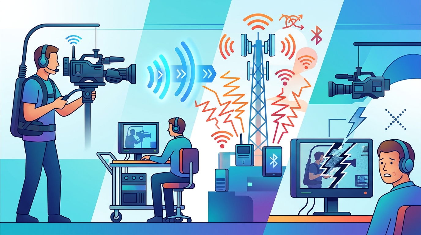
The most useful engineering decision is therefore to identify the type of failure before changing equipment settings. Weak reception calls for a different investigation from a crowded RF environment. A camera-position-dependent interruption suggests a different problem from a failure that occurs across every camera. Likewise, a stable wired video path provides valuable evidence when determining whether the wireless transmission is actually responsible.
Professional wireless video infrastructure becomes more dependable when RF coordination, antenna installation, environmental assessment, receiver diagnostics, and documented troubleshooting procedures are treated as connected parts of the production workflow.
For production engineers and broadcast teams, the central lesson is straightforward: a transmitter and receiver do not operate in isolation. Their performance depends on the complete electromagnetic environment surrounding them. Understanding that environment turns unexplained signal drops into identifiable engineering problems—and makes it possible to protect the continuity of demanding professional video productions.


Comments
Post a Comment