What Hidden RF Interference Challenges Threaten Pro Wireless Video Feeds in Dense Production Environments?
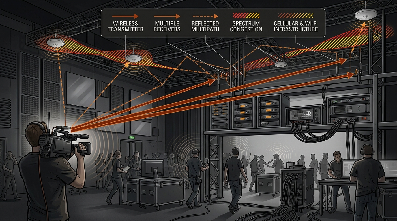
RF interference wireless video production becomes a different engineering problem when a camera is no longer operating in an empty room. A modern stage, sports venue, outside-broadcast compound, virtual-production volume, or convention hall can contain wireless cameras, microphones, intercoms, Wi-Fi access points, cellular devices, remote-control systems, lighting electronics, telemetry, and other RF emitters at the same time. The most troublesome failures are often not caused by one obviously incompatible transmitter. They emerge from the interaction between spectrum occupancy, receiver sensitivity, antenna geometry, reflections, moving people and equipment, and the changing electrical environment of the venue.
That distinction matters. A link that works perfectly during a quiet setup can develop frozen frames, block errors, latency spikes, retransmissions, or complete loss of picture once the production fills with people and equipment. The European Broadcasting Union's recent work on video Programme Making and Special Events (PMSE) describes wireless cameras and portable video links as important production applications that depend on appropriate radio-spectrum access. r1 The practical lesson is that wireless video reliability should be treated as an RF-system problem rather than simply a question of transmitter range.
Why Dense Production Environments Behave Differently
RF conditions inside a production venue are rarely static. The camera may move from a clear aisle into a corridor lined with metal structures, behind a lighting truss, around a vehicle, or into a crowd. Every change alters the electromagnetic channel. Walls, stages, LED panels, truss, scenery, camera carts, vehicles, and even large groups of people can change how energy reaches the receiver.
The first hidden challenge is multipath. The receiver does not necessarily see one clean copy of the transmitter's signal. It can receive a direct path plus several reflected or diffracted copies arriving with different delays and phases. Depending on frequency and geometry, those components may reinforce one another or partially cancel. The result can be a location where the signal is strong a few feet away but unexpectedly weak at the camera position.
This is one reason a simple range test can be misleading. A transmitter can have sufficient nominal power and still experience a deep local fade. Moving the camera, receiver antenna, or an obstruction by a small distance may change the result dramatically. Modern multicarrier systems can tolerate substantial channel variation, but they are not immune to time-varying multipath. IEEE technical material explains that changes in multipath and Doppler conditions can disrupt subcarrier orthogonality and produce intercarrier interference in OFDM systems. r2
The Interference Sources That Are Easy to Misdiagnose
Adjacent and near-band transmitters
The obvious suspect is another transmitter operating on a nearby frequency. But the important variable is not simply whether two devices use different channels. A high-power nearby transmitter can raise the RF environment presented to a receiver even when its assigned channel does not overlap the desired signal. Receiver filtering, transmitter spectral cleanliness, antenna coupling, separation, and physical distance all influence the outcome.
Receiver overload
Another subtle failure mode is front-end overload. Engineers sometimes respond to a weak or unstable picture by adding gain, relocating an antenna, or increasing transmitter power. If the real problem is an excessively strong nearby signal entering the receiver, those actions can make the situation worse. The receiver's sensitive front end has to distinguish the wanted signal from everything else arriving at its input.
Unintentional emissions from production electronics
RF problems do not always originate in equipment described as a radio transmitter. Switching power supplies, digital electronics, LED lighting systems, computers, motor controllers, video processors, network equipment, and poorly controlled electrical assemblies can contribute electromagnetic noise or harmonics. The EBU's electromagnetic-compatibility work explicitly considers harmful interference arising not only from licensed services but also from the growing range of electrical and electronic devices used in everyday environments. r3
Shared spectrum and the crowded production ecosystem
A professional production often operates as a temporary RF ecosystem. Wireless cameras may coexist with microphones, in-ear monitors, intercoms, Wi-Fi, cellular services, and other systems. The FCC has likewise described production environments as using wireless systems across shared bands alongside other wireless services. r4 Ofcom's 2026 PMSE review identifies wireless cameras among the production applications whose spectrum requirements are increasing. r5
Propagation Patterns: Why the Problem Moves When the Camera Moves
Propagation is often the missing explanation when a crew reports that “the link dies in one spot.” In a dense venue, RF energy can bounce between hard surfaces, pass around obstacles, and become partially blocked by structures. A camera operator moving through the set therefore changes the channel continuously.
Consider a camera crossing an arena floor. In one position, the receiver may have a strong direct path to the remote antenna. A few meters later, the camera may be screened by a truss column while reflected energy continues to arrive from several directions. If the reflected components combine destructively, received signal quality can fall much faster than the physical distance between camera and antenna would suggest.
Motion introduces another dimension. The relative movement of cameras, vehicles, antennas, and people can make the channel time-varying. For systems using multicarrier modulation, Doppler-induced changes can contribute to intercarrier interference when channel conditions change sufficiently quickly. This does not mean every visible dropout is Doppler-related; it means motion can interact with an already marginal RF path and make a previously stable link less predictable.
No-Cost Fixes Before Buying Another RF Device
The most valuable intervention is often not another transmitter. Before spending money, establish whether the failure follows frequency, location, orientation, equipment state, or physical movement. That simple discipline prevents a common production mistake: treating every RF symptom as a range problem.
Start by documenting the exact conditions under which the picture fails. Record camera position, receiver position, antenna orientation, active wireless systems, lighting state, Wi-Fi activity, and notable venue changes. Repeat the same route while changing only one variable at a time. If the failure follows the camera's location, suspect propagation. If it follows another transmitter's activation, suspect coexistence or overload. If it appears after a cable or antenna change, investigate the RF chain before blaming the spectrum.
Physical separation is another no-cost or low-cost lever. Where practical, avoid placing a sensitive receive antenna immediately beside unrelated high-power RF equipment. Keep antennas away from large conductive structures when the installation allows it, and avoid casually burying an antenna behind racks, video walls, or metal scenery.
Frequency coordination should also happen before the production becomes fully populated. The EBU notes that PMSE frequency ranges and requirements vary across national frequency plans, while Ofcom's work illustrates the broader trend toward more deliberate spectrum coordination as wireless production demand grows. r6 The correct operating frequencies and permitted power levels are jurisdiction-dependent, so production teams should use the applicable local regulatory framework rather than copying a frequency plan from another country.
When Measurement Tools Actually Help
A measurement tool becomes valuable when the team has exhausted basic isolation and the cause remains ambiguous. A spectrum analyzer can reveal whether the environment contains persistent carriers, intermittent bursts, broadband noise, unexpected emissions, or unusually strong nearby signals. The point is not to stare at a waterfall display and guess. The measurement should answer a specific question.
If a dropout occurs at a repeatable time, a time-correlated spectrum observation can help establish whether another RF event coincides with it. If the problem occurs only in one physical location, a spatial scan can help distinguish propagation loss from broad spectrum congestion. If receiver performance worsens when a nearby transmitter becomes active, measuring the input environment can help separate overload from ordinary low signal-to-noise performance.
A directional antenna can also turn an RF investigation into a spatial exercise. If an unwanted emission becomes stronger as the antenna is rotated toward one part of the venue, the crew gains evidence about its direction. This is particularly useful when the suspected source is not an obvious radio device.
However, measurement equipment has a limitation: it observes the measurement setup, not necessarily the exact internal state of the production receiver. A spectrum analyzer with a different antenna, bandwidth, noise floor, preamplifier, or placement may see something the receiver does not experience in the same way. Measurements therefore become more useful when their configuration resembles the real RF path being diagnosed.
Pre-Purchase Checks That Prevent Unnecessary Spending
Before acquiring additional hardware, ask three questions. First, can the failure be reproduced? Second, can the failure be correlated with a specific frequency, location, transmitter, or physical configuration? Third, is the existing system operating within its documented electrical and RF limits?
If the failure is strongly location-dependent, prioritize propagation and antenna geometry analysis before buying a more powerful transmitter. If the failure appears whenever a neighboring RF system activates, prioritize coordination, filtering, separation, and receiver overload analysis. If the failure remains unexplained after controlled tests, a measurement instrument may provide more value than immediately replacing the wireless video system.
This decision logic matters because “more range” and “more reliability” are not synonymous. A higher-power transmitter can increase the desired signal, but it can also increase interference potential, reduce coexistence margins, or exceed applicable operating constraints. Likewise, a new receiver may provide better filtering or sensitivity, but it cannot eliminate a severe propagation null created by the venue itself.
Who benefits most from measurement equipment?
Dedicated RF measurement is most defensible for crews that repeatedly work in different venues, operate many simultaneous wireless systems, troubleshoot intermittent failures under deadline, or maintain a production infrastructure where recurring RF problems have significant operational cost. It is less compelling for a simple, fixed installation with a known RF environment where the actual issue is a loose connector, poor antenna placement, or an incorrectly configured channel.
Where the cheaper choice can be better
If a repeatable test shows that the problem disappears when an antenna is moved away from a metal obstruction, the highest-value solution may be a mounting or placement change rather than new electronics. If a cable inspection reveals damage or an unreliable connector, replacing the physical RF path may solve the problem more directly than changing the wireless system. The right investment is therefore the one that removes the identified failure mechanism, not the one with the most impressive RF specification.
Practical Action Checklist for a Dense Production RF Environment
- Document every active wireless system before troubleshooting the video link.
- Record the exact location, antenna orientation, and physical surroundings when the failure occurs.
- Repeat the route or camera movement to determine whether the problem follows geography.
- Change one RF variable at a time so cause and effect remain visible.
- Temporarily disable suspected nearby transmitters where operationally and legally possible.
- Check whether additional RF gain improves the link or instead increases instability.
- Inspect connectors, cables, adapters, and antenna mounting before replacing active electronics.
- Review local spectrum rules and production-frequency coordination requirements.
- Use spectrum measurement when the cause cannot be distinguished through controlled isolation.
- Record successful frequency, antenna, and placement configurations for repeat deployments.
Usage Cautions: The RF Fix Can Become a New RF Problem
Every mitigation technique has a boundary. Increasing power can improve a marginal link but can also increase interference with other systems. Narrower filtering can reject unwanted energy but may be inappropriate if it clips required bandwidth. Directional antennas can improve spatial isolation but may make a moving camera's coverage less uniform. Antenna diversity can reduce sensitivity to localized fades but adds complexity and does not magically create spectrum.
Another important exception is the difference between interference and ordinary system failure. A frozen video feed can originate in the camera, encoder, network path, decoder, storage subsystem, power supply, or thermal condition. An RF symptom should not automatically be assigned an RF cause. A disciplined troubleshooting sequence therefore compares RF indicators with the system's internal link-quality information and with non-RF logs whenever those diagnostics are available.
There is also a regulatory boundary. Frequency allocations, permitted power, licensing requirements, and equipment rules differ by country and sometimes by operating context. A frequency that appears suitable in one production market may not be lawful or appropriate in another. Spectrum planning is therefore both an engineering activity and a compliance activity.
Why Spectrum Coordination Is Becoming a Production Infrastructure Issue
Wireless video is increasingly embedded in production workflows rather than treated as an isolated camera accessory. EBU research describes a growing mix of wireless production applications, while Ofcom's 2026 PMSE review specifically considers the future spectrum needs of wireless cameras and other production systems. r7 This trend means RF planning increasingly belongs alongside power distribution, networking, intercom planning, camera logistics, and venue infrastructure.
The emerging challenge is not simply finding an empty channel. It is creating enough predictable RF margin for a collection of systems that may change throughout the day. A production can move from a quiet rehearsal to a crowded live show without changing the nominal wireless-video configuration, yet the RF environment can become dramatically more complex.
That is why spectrum occupancy, antenna geometry, propagation mapping, receiver behavior, and equipment coexistence should be considered together. Automated coordination approaches in other shared-spectrum contexts similarly show that location and technical parameters can influence what spectrum use is feasible. r8 The broader principle applies to production engineering: RF availability is contextual, not merely a label printed on a device.
FAQ: Hidden RF Interference in Professional Wireless Video
1. Why does wireless video fail in only one part of a venue?
The most likely explanations include multipath, obstruction, antenna nulls, and local changes in the RF environment. A strong signal measured elsewhere does not prove that every position has a strong and stable propagation path. Repeating the camera movement while changing antenna position is a useful way to distinguish a localized propagation problem from a broader spectrum problem.
2. Can a nearby Wi-Fi or cellular device disrupt professional wireless video?
It can, depending on frequency relationships, power levels, physical proximity, receiver filtering, antenna coupling, and the specific equipment involved. The important point is not to assume interference solely from the device category. Measure or isolate the suspected source and determine whether the video failure correlates with its operation.
3. Does increasing transmitter power solve RF interference?
Not necessarily. More transmit power can improve a weak desired signal in some situations, but it cannot reliably repair a propagation null or a receiver suffering from strong unwanted signals. It can also create additional coexistence or regulatory concerns. Power should therefore be treated as one variable, not the universal remedy.
4. Why can moving an antenna a small distance help so much?
Because multipath creates spatially varying interference patterns. Reflected signals can reinforce or cancel the direct path at different positions. A small physical change can therefore alter the phase relationship among arriving signals and move the receiver out of a local fade.
5. When is a spectrum analyzer worth using?
It becomes valuable when controlled changes cannot identify whether the problem is another transmitter, broadband noise, intermittent interference, overload, or spectrum congestion. It is especially useful for recurring productions where the cost of diagnosing RF failures under deadline is high. For a simple connector fault or obvious antenna obstruction, measurement may be unnecessary.
6. Can a spectrum analyzer prove that the wireless receiver is healthy?
No. A spectrum analyzer characterizes the RF environment presented to its own measurement chain. The receiver has its own filtering, gain structure, demodulation behavior, antenna, and installation geometry. A good spectrum trace can narrow the possibilities, but it does not replace end-to-end system testing.
7. Is antenna diversity a complete solution for multipath?
No. Diversity can reduce the probability that all receive paths experience the same deep fade, but its effectiveness depends on antenna spacing, orientation, receiver architecture, propagation conditions, and installation quality. Severe interference or receiver overload can remain even when diversity is present.
8. What is the first thing to check before buying a new wireless video system?
Reproduce the failure and determine whether it follows frequency, location, antenna position, another transmitter, or a physical cable path. If the cause is already visible, correcting that cause is generally more rational than replacing a complete system. If the cause remains ambiguous after controlled tests, measurement and RF coordination may provide more useful information than immediate replacement.
Information Synthesis: Treat the Wireless Link as Part of the Venue
The hidden RF challenge in professional wireless video is that the transmitter and receiver are only two components of a much larger electromagnetic system. The venue contributes reflections and obstructions. Other wireless systems contribute competing energy. Lighting and digital equipment can contribute electromagnetic emissions. Human movement changes propagation. Antennas turn physical placement into an RF design decision, while regulatory rules determine which parts of the spectrum can actually be used.
The practical sequence is therefore diagnostic rather than product-driven: reproduce the failure, map where and when it occurs, isolate likely sources, inspect the physical RF path, verify spectrum conditions, and only then decide whether additional equipment is justified. If a no-cost placement change fixes a multipath problem, buying a higher-power transmitter adds unnecessary complexity. If repeated productions expose unpredictable interference that cannot be diagnosed by observation alone, measurement and formal coordination become much more defensible investments.
For dense production environments, reliability comes from preserving RF margin and understanding why that margin disappears. The most robust wireless video workflow is not the one that assumes a clear channel will remain clear. It is the one that expects the RF environment to change and has a method for recognizing, measuring, and correcting those changes before they become a live-production failure.


Comments
Post a Comment